I have Fender Champ silverface in my stock. It has been modified already by myself.
MOD = Vibrato circuit was disabled. Grill cloth was replaced with gold one.
 |
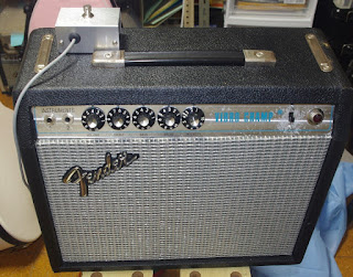
SF Champ in my stock, already modified. Front view
|
MOD = AC Inlet has been added. Speaker Jack has been changed to phone from RCA and relocated on the back panel.
 |
SF Champ rear view
|
MOD = CT has been added instead of decoupling resistor 1K ohm 1W.
The power amp stage is still single ended 6V6 though.
One preamp tube has been added for more gain stage.
 |
| CT( Choke Transformer ) and a pre tube has been added |
MOD = Removed circuit board. Wired resistors and capacitors using terminal strips.
Used multiple axial electrolytic capacitors instead of multi section electrolytic.
 |
| Circuit has been remounted completely |
All mods were for experimental purposes to determine the sound difference.
And the data was captured. The experiment has been done.
So, it's the time to restore the amplifier.
Restoring back to the original Champ is not so interesting or enjoyable.
I wanted more joy.
Well, PT of the Champ and the Princeton is the same.
The same voltage and the same current value.
So if I replace the OT with one for Pushpull and if I add a US tube socket for another 6V6, I will be able to convert the Champ to Princeton !!! Need the circuit modification too of course.
 |
Fender amplifier's transformers
|
decided to restore my scratched Champ to Princeton amp.
Step 1. Speaker
When the experiment has been performed Original speaker was replaced with Jensen 8" ceramic.
 |
| Original speaker has been replaced with Jensen ceramic |
During the experiment, it was replaced with Fender replacement 8" speaker.
It is probably made by Eminence.
 |
| Then after mounted Fender Replacement speaker |
This time, replaced with the 10" Celestion. Speaker hole is the same as 8", but added extra screw holes for mounting 10 inch speaker.
 |
| 10 inch celestion has been installed |
Step 2. Transformer and other elements
Removed CT.
Replaced OT from SE Champ to one for PP 17W 8K-8Ohm.
Installed one US tube socket.
Installed electrolytic multisection capacitor (F&T 36microfalad x2 )
Removed extra preamp tube socket
 |
| Chassiss top view difference |
Step 3. Circuit Modification
Installed circuit board instead of terminal strips
Reduced electrolytic axial capacitor's quantity by using multi section.
Revived vibrato circuit
Assembled GAMPS original circuit inspired by AA964 Princeton.
Coupling capacitors are Orangedrop film, Murata ceramic and Sizuki film.
Resistors are 1W Ohmiote for power and 1/2W Kamaya carbon composition
 |
| Circuit view |
Step 4. Bias adjust
Differing from AA964, this amplifier has bias depth adjustment pot.
Adjusted the pots by refering to 6V6 plate voltage and by measuring 6V6 cathode current.
A little colder setting.
 |
| Bias adjust |
Step 5. Facade change
Replaced gril cloth with silver one from yellowish one
Speed and Intensity pot returned.
 |
| Front view before and after |
Step 6. Rear view change
removed AC inlet--- power cord is inserted chassis under
removed speaker phone jack--- RCA speaker jack is located under
added a toggle switch.
This switches pentode mode and ultra lenear mode of OT and power tube operation mode.
 |
| rear view before and after |
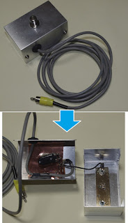
Step 7. Made original foot switch for vibrato on off.
Made the original foot switch for vibrato on/off.
Box itself is made of alminum to get lighter weight.
In order to lower the noise, put extra metal, brass and cupper for emphasizing zero volt grounding level of the switch box.
 |
| Vibrato foot switch facade and inside |
Step 8. completion
Outer facade is The Fender Vibro Champ silverface and the circuit is modified to Princeton amp.
 |
| Front view |
 |
| Rear view |
Will post the sound clip of the amplifier soon.
Hope you're going to have the nicest guitar playing life. Thank you.


